
Installation fails when the cover is sized from axis stroke alone or fastened off-centre. You will learn how to identify the fixed and moving ends, calculate the working length, mount the cover without distorting its folds, and prove that it moves freely before production begins.
Key takeaways
- Identify the fixed housing, moving carriage and travel axis before ordering.
- Calculate working length from compressed length, extension and machine travel.
- Attach both ends without pulling, twisting or loading the bellows fabric.
- Test full travel concentrically, then record operating conditions and inspection intervals.
Confirm the axis, attachment points and cover type before ordering
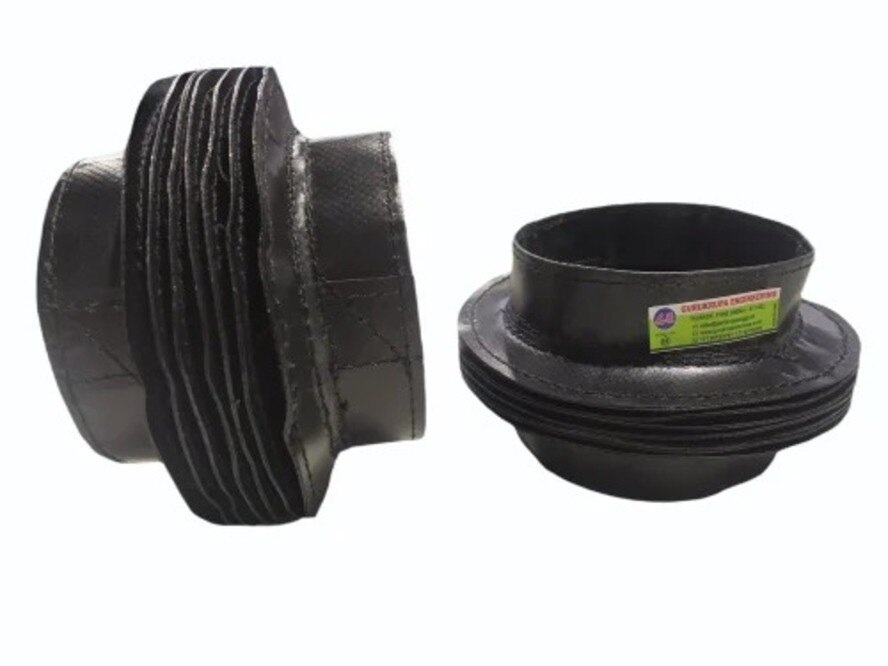
A cylindrical bellows cover fits an axial or rotating spindle, shaft, screw or rod when the protected component moves concentrically inside the cover. Identify the stationary housing, the moving carriage and the travel axis before ordering: attach the fixed end to the machine frame, and attach the following end to the moving component.
Reversing them makes the folds resist the intended motion.
Record the axis orientation, travel direction, speed, acceleration and machine overtravel. Inspect the mounting surfaces for a flat flange, threaded collar, end ring, bracket or adapter plate, then confirm shaft clearance and space for every fold at full compression. The cover protects and seals; it is not a bearing, guide or drive element.
Use this comparison before selecting how cylindrical bellow covers are installed:
| Option | Suitable arrangement | Reject it when |
|---|---|---|
| Cylindrical bellows | Concentric axial or rotating motion | The path is offset, twisting or changes shape |
| Rectangular or three-sided cover | Broad guideway access | The protected part is a narrow round shaft |
| Telescopic cover | Rigid, segmented protection | Flexible folds are needed around an irregular path |
| Accordion bellows | Guided axial expansion and contraction | Its fold direction does not match travel |
- Name the protected spindle, shaft, screw, rod or guideway.
- Mark the stationary housing and moving carriage on the machine drawing.
- Confirm whether side access or a large radial opening is required.
- Reject the cylindrical type if the cover must twist or the available space is non-concentric.
A flat or angled mounting surface needs an adapter plate; never force the bellows to match an incorrect bolt pattern.
Take the measurements and calculate working length
Accurate round bellow cover fitting requires the machine’s actual closed length at the reference position and required extended length at the far travel limit. Do not size the cover from nominal axis stroke alone: include usable stroke, machine overtravel, mounting-face positions and the space occupied by the end fittings.
- Outside and inside diameter
- Shaft or spindle diameter
- Mounting-face diameter and flange depth
- End-ring thickness
- Radial clearance around every fold at full compression
- Fold pitch and number of end folds
- Adapter thickness
- Clearance to adjacent parts
Calculate required cover stroke as machine travel plus any overtravel the cover will actually encounter. Select compressed length from the available machine space, then select an extended length that covers this stroke while preserving the maker’s specified overlap at both ends.
Add a safety margin, but stay within the stated minimum compressed length and maximum extended length.
Ask the manufacturer to confirm permitted compression, extension, speed, acceleration and mounting orientation for the exact construction. Fold pitch, fabric reinforcement and end fittings change these limits; no universal safe compression ratio exists. A cover that clears the shaft can still rub when its folds expand sideways.
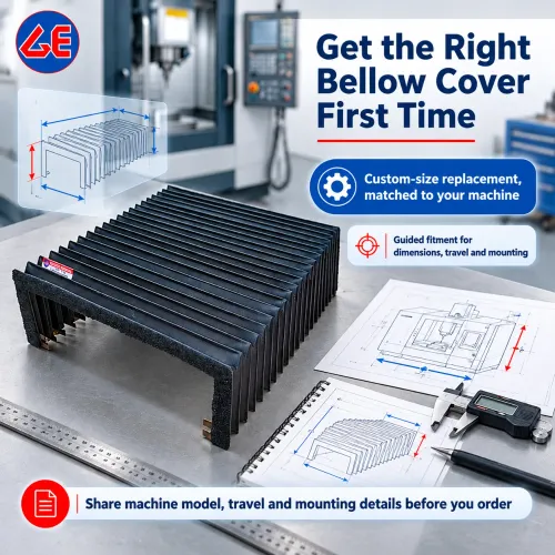
Draw the cover envelope at both travel limits. Mark bolt holes, clamps, seals, drainage paths, nearby chips and coolant lines before ordering. This drawing exposes interference that a diameter or stroke figure alone will miss.
Install the fixed and moving ends without loading the fabric
Install the fixed end on the stationary housing and the moving end on the carriage, spindle or rod. This cylindrical bellow cover installation sequence prevents the fabric from carrying mounting or guidance loads.
1. Shut down the machine, isolate every energy source and apply lockout. Remove guards only far enough to reach the mounting faces.
2. Clean the shaft, housing and adapter surfaces. Inspect the cover for torn fabric, crushed folds, loose stitching, damaged coating and bent end rings. Reject damaged parts before fitting.
3. Install the fixed-end flange, collar, clamp, bracket or end plate on the stationary housing. Transfer clamping force through the end ring or purpose-made fitting, never through a pleat wall.
4. Position the moving-end adapter at the machine’s known reference position and align it with the protected axis. Attach the moving end while the bellows is relaxed; do not stretch, twist or rotate it to match a seam or bolt pattern.
5. Use an adapter plate when the machine face does not match the supplied fitting. Do not drill through the bellows body, clamp over a fold or tighten a fastener against unsupported fabric.
6. Tighten flange fasteners gradually in a cross-pattern and check that the end ring remains flat.
7. On long horizontal or vertical covers, install the specified guide rod, support tube, carrier or anti-collapse arrangement. The bellows must follow the motion, not carry the moving component.
Align concentrically and test the complete travel
Install cylindrical bellow covers concentrically around the spindle, shaft, guideway or rotating component, then test the complete travel before applying production speed. Compare the gap around the circumference at both ends. An uneven gap identifies an offset collar, angled end plate or misaligned adapter.
Rotate the component by hand when possible. Next, move the axis slowly through its full programmed travel with power isolated, or at low speed under the machine builder’s test procedure. Watch every fold for progressive, even compression and extension.
| Sign during test | Likely cause | Required response |
|---|---|---|
| Uneven opening or localized fold collapse | Offset mount, unequal compression or insufficient guidance | Correct the mounting faces or add the specified guidance |
| Scraping, shiny coating, fabric dust or chips on one side | Rubbing or inadequate clearance | Increase clearance and inspect adjacent parts |
| Sharp drive-load change or sideways carriage pull | Cover too short, stiff seam or side load | Revise the length or mounting arrangement |
Stop if the cover contacts a guard, screw, cable, coolant line or adjacent fold. Do not force alignment by tightening one side. Confirm that full compression leaves the end fittings clear and full extension retains the required overlap.
Repeat the test after refitting guards. A guard or hose can deflect into the moving cover and create rubbing that was absent during the initial check.
Specify the operating environment and service checks
After fitting, verify that the cover survives the machine’s actual environment and moves without adding side load. For cylindrical bellows for precision machines in Mumbai, record coolant, cutting oil, cleaning chemical, ambient and machine-generated temperature, UV exposure, abrasive chip type, wash-down method, axis orientation and service-access limits.
- Match the fabric, elastomer coating, thread, adhesive and end-ring material to those recorded chemicals, temperatures and abrasion conditions. Chemical incompatibility can destroy a correctly sized cover.
- Record humid and monsoon exposure. Inspect steel end rings, clamps and fasteners for corrosion, and provide a drain path or drying access wherever water can collect.
- Retain wipers, scrapers, shields or a chip conveyor when the machine produces hot swarf or abrasive debris. A cylindrical cover shields a shaft or screw; it does not manage every chip.
- During commissioning, compare axis load or following error with the cover detached and installed, but only if the machine builder permits that test. A new measurable side load indicates an offset mount, unequal fold compression, stiff seam or insufficient length.
- Inspect folds, seams, end rings, clamps, drainage paths and rubbing marks after initial running and after coolant or tooling changes. Set the next interval from duty, chip load and wash-down frequency.
- Give a Mumbai supplier the measured closed and extended lengths, diameters, flange geometry, axis data, chemicals, temperatures and service-access limits. Consider GURUKRUPA BELLOWS PVT LTD alongside other suppliers only after its proposed end fittings and operating limits match those records.
Related products
 | Bellow Cover The range of CNC Bellow Cover is manufactured on our premises, under the guidance of our expert professionals. View product → |
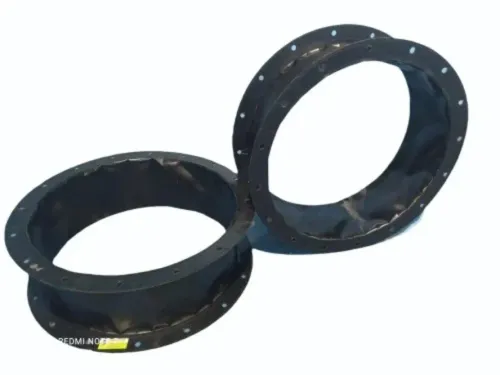
 | Round Bellow Covers ₹1000 To match with our reputation in the market, we are here to present an unparalleled assortment of Round Bellow Covers. View product → |
Frequently asked questions
Which machine details must you confirm before ordering a cylindrical bellow cover?
Confirm the protected axis, stationary housing, moving carriage, attachment points and whether the cover protects an axial or rotating component.
How do you calculate the working length of a cylindrical bellows cover?
Measure the machine travel and allow for the bellows compressed length, extended length, mounting clearances and the required movement range.
How should you attach a cylindrical bellow cover?
Fix one end to the machine frame and the other to the moving component without stretching, twisting, crushing or loading the fabric.
How do you check alignment after fitting a round bellow cover?
Align the cover concentrically with the spindle, shaft, screw or rod, then run the complete machine travel and check for rubbing, buckling and uneven folds.
What operating conditions should you provide when specifying cylindrical bellows for precision machines in Mumbai?
State exposure to dust, chips, coolant, oil, heat, sparks, moisture and corrosion, then define service checks for wear, attachment security and fold movement.
Related product
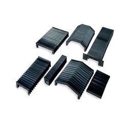 | CNC Bellow Cover Product Details: Brand GURUKRUPA Color BLACK Size ANY We are considered a well-known name in the business that manufactures and supplies CNC Bellow... View product → |