
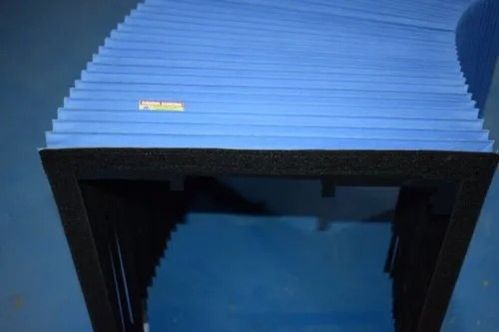
A CMM bellows project begins with the machine’s complete motion envelope, not with a guideway length copied from a catalogue. You will see how measurements become a low-friction cover, how the assembly is tested across full travel, and which information you need before requesting a quotation or approving installation.
Key takeaways
- Start with the CMM’s full axis motion envelope, not only the exposed guideway.
- Match fabric, coating and fold geometry to debris, heat, friction and measurement accuracy.
- Check fold count, mounting points and clearances against every axis position.
- Approve the finished bellows after fit, movement and probe-clearance inspections.
How the machine’s motion becomes a bellows design
The first manufacturing stage turns the CMM’s complete motion envelope into a bellows design, not just a cover over the exposed guideway. The review examines the CMM drawing, axis stroke, bridge movement, guideway arrangement, scale position, probe clearance, cable and hose routes, and surrounding enclosure.
The supplier records:
- Extended and compressed length, open height, maximum width, fold pitch and travel direction.
- Bend radius, allowable transverse or diagonal movement, and clearance at full extension, compression and intermediate travel.
- End-frame geometry, mounting-hole locations and the complete clearance envelope.
Guideway dimensions alone are inadequate. A cover can bind during diagonal movement or intermediate travel even when its end positions appear correct, then rub a scale, probe, bridge component or enclosure before the programmed stroke ends. The review also checks cable and hose interference during acceleration and deceleration.
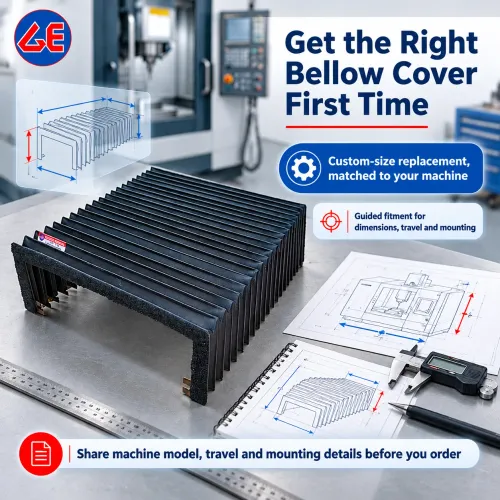
For a quotation, submit the machine model, a marked-up drawing, photographs, travel data, mounting details, service-access limits and photographs of cable routing. These records show whether the request is a replacement-in-kind or a redesign.
A replacement copies proven dimensions; custom CMM bellows require new fold counts, support elements or end frames when travel, routing, access or the inspection environment has changed. The final drawing must show those decisions before fabrication begins.
How materials and folds are built for precision measurement
A CMM cover is a light layered assembly, not a solid molded part. Coated polyester or polyamide fabric supplies the barrier; backing cloth stabilises it, reinforcement controls shape, flexible joints allow motion, and wear strips protect rubbing zones. Support slats and end frames prevent sag without loading the machine.
| Coating | Flexibility | Cleaning, abrasion and temperature considerations |
|---|---|---|
| PVC | Moderate | Check cleaner compatibility, abrasion resistance and stated operating range |
| Polyurethane | High | Good flex life; demand chemical and abrasion test evidence |
| Rubber | Flexible and resilient | Check swelling, ageing, particle shedding and temperature limits |
| Silicone | Very flexible | Wide temperature capability; verify abrasion and cleaning performance |
Require the supplier to name the exact coating, thickness, operating range and chemical-test evidence. “Chemical resistant” is not enough.
Sewn seams tolerate awkward shapes but stitch perforation can admit contamination. Adhesively bonded seams avoid needle holes but can age or soften under cleaners. Heat-welded and RF-welded seams form continuous joints when the coatings are compatible; uncontrolled heat can embrittle the fabric.
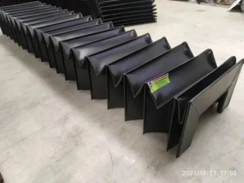
Fold height and pitch set stroke and compressed-pack height. Fold radius limits local strain, while fold count trades lower strain against a taller pack, longer production and more particle traps.
Unlike heavy-duty CNC covers, CMM machine protection prioritises low mass, low friction, controlled collapse and non-abrasive surfaces. The cover must not touch granite tables, scales, air bearings, probes or moving bridge components.
How fold count, mounting parts and clearances are calculated
Turn measured travel into a cut pattern by calculating the required extended length as working stroke plus fixed end allowances and attachment slack. Calculate compressed length as the folded pack plus frame thickness and clearance thickness.
Fold count equals usable stroke divided by the movement contributed by each fold. Set that movement from the selected fold pitch and bend radius; changing either alters the pack height, local strain and collapse behaviour.
The supplier must confirm these figures on a dimensioned drawing, not a generic “any size” description, before cutting custom cmm bellows or measurement machine bellows.
Fabricate the mechanical assembly to preserve fold alignment and service access. It can include end frames, flanges, rails, clamps, screws, hook-and-loop attachments, adhesive flanges and removable service panels. On long horizontal spans, guide strips, wear-resistant runners and support slats prevent sag and buckling, but they add moving mass and friction.
Check the complete assembly against the following points:
- Fasteners do not protrude into folds, cables or guideways.
- Attachment slack is sufficient without allowing uncontrolled movement.
- Frames and rails do not over-constrain the body.
- Attachment orientation matches the travel direction.
- Every fold stays within its specified bend radius.
- Cables and hoses cannot enter a pinch point.
- Clearance remains at full compression, full extension and maximum lateral offset.
How the finished assembly is fitted and inspected
Fit the flexible body between the fixed and moving frames at mid-stroke, with folds centred and the end frames square to the travel axis. Tighten clamps, flanges or screws gradually in a cross-pattern; over-tightening one side skews the folds and creates rubbing at the next stroke.
Leave removable panels and planned gaps for scales, cables, hoses and probe components.
Record acceptance against the approved drawing, not visual appearance alone:
- Dimension: compressed length, extended length, open height, overall width, fold alignment and mounting-hole position.
- Visual: continuous seams, no delamination, loose threads, adhesive residue or damaged coating.
- Movement: no rubbing, pinching, sag or unwanted light gaps; repeatable travel without sticking.
- Installed motion: cycle the complete stroke through intermediate positions, maximum transverse movement and acceleration or deceleration effects, with every cable and hose fitted.
Test coolant, oil, cleaning chemicals, humidity, temperature, fire performance and particle shedding when those hazards exist. Put the exposure, duration, temperature and pass condition in the purchase specification; no single standard covers every measurement machine bellows requirement.
A bellows is a flexible barrier, not a hermetic seal. Fold valleys, frames and moving overlaps remain leakage paths, so fine airborne contamination may require overlapping skirts, wipers, sealed ends or controlled airflow. Confirm these details before accepting the cmm machine protection assembly.
How to approve, install and maintain the protection
Approve cmm machine bellow covers only after the supplied assembly matches the machine, the acceptance criteria, and the recorded travel test. Require these documents before release:
- Current drawing revision with dimensions and mounting details
- Material, coating, thickness and seam specification
- Sample or prototype fit record
- Measurable acceptance criteria
- Complete-stroke cycle-test record
- Inspection photographs
| Option | Select it when | Main constraint |
|---|---|---|
| Bellows | Fine dust, limited space and low bridge force | Not a hermetic seal |
| Telescopic covers | Chips or liquid need rigid containment | Require more space and mass |
| Brush strips | Larger dry particles need simple wiping | Pass fine dust and add contact drag |
| Sliding shields | Broad surfaces need guarded access | Need guide clearance |
| Enclosures | Airborne contamination or liquid is severe | Restrict access and increase size |
| Scheduled cleaning | Contamination is light and predictable | Does not protect during operation |
Install cmm bellow covers with the CMM in its final configuration, including cables, hoses and accessories. If the cover changes bridge loading, drag or contact, repeat the manufacturer’s geometric performance check under ISO 10360 acceptance or reverification procedures.
Inspect creases, seam transitions, end attachments, rubbing points, coating chalking, lint, sag and trapped contamination. Repair only defects that cannot affect movement or measurement; replace the cover for cracking, delamination, seam separation or permanent deformation.
GURUKRUPA BELLOWS PVT LTD can use drawings, photographs and travel data to separate custom cmm bellows from replacement-in-kind work, expose prototype and downtime lead-time drivers, and assign final alignment responsibility.
Related products
 | Bellow Cover ₹1000 Product Details: Brand GE Color Black-Blue - Gray -White Size ANY ( C shape, Square, Round, Rectangular) Ours is a trustworthy name in the business... View product → |
 | CNC Bellow Cover Product Details: Brand GURUKRUPA Color BLACK Size ANY We are considered a well-known name in the business that manufactures and supplies CNC Bellow... View product → |
Frequently asked questions
How does CMM motion determine the bellows design?
Designers review the CMM drawing, axis stroke, bridge movement, guideway layout, scale position, probe clearance and cable and hose routes. The bellows must cover the complete moving envelope without restricting travel or measurement access.
Which materials and construction details support precise CMM measurement?
The material and coating must suit the machine’s debris, temperature, friction and cleaning conditions. Fold construction must remain stable, avoid scale or probe interference, and move without transmitting unwanted force to the measuring structure.
How are fold count, mounting parts and clearances calculated?
Calculate fold count from the required compressed and extended lengths, then check mounting points, guideway coverage, bridge travel, scale access, probe clearance, cable routes and surrounding enclosure at every axis position.
What should you inspect before approving and installing CMM bellows?
Inspect dimensions, fold consistency, stitching or bonding, mounting hardware, surface condition and movement. During installation, confirm alignment, unrestricted travel, secure fasteners and clearance from scales, probes, cables and hoses. Maintain the covers by removing debris and checking attachment points and wear.
Related product
 | Round Bellow Covers ₹1000 To match with our reputation in the market, we are here to present an unparalleled assortment of Round Bellow Covers. View product → |