
A ball screw bellow cover is sized around the moving nut, fittings, mounting interfaces and full machine stroke—not just the screw’s nominal diameter. By the end, you will have a measurement checklist, a sizing method, operating limits to state, and an acceptance specification you can send to a local supplier.
Key takeaways
- Measure the nut, return tube, clamps and bearing support at both travel limits.
- Calculate compressed length, extended length and usable travel before requesting a quote.
- Specify mounting faces, material, coolant exposure, speed and sag limits.
- Send a dimensioned drawing with measurable fit and performance acceptance criteria.
Measure the complete moving envelope before requesting a quote
A screw’s nominal outside diameter does not define the ball screw bellow cover size. Measure the complete moving envelope around the nut and record the machine positions at both travel limits, because a cover that clears the shaft can still strike a return tube, clamp or bearing support.
1. Record the screw outside diameter, exposed screw length, ball-nut length, width and maximum height. Include return tubes, deflectors, lubrication fittings, wipers, clamps and nearby support hardware in the maximum envelope.
2. Mark the fixed machine datum, moving-nut datum and both end-of-travel positions. Measure required travel, available collapsed space, maximum extended space and clearance to every surrounding surface.
3. Measure each mounting face: flange length and width, hole spacing, hole diameter, bolt size, collar or clamp arrangement, and available mounting depth. State which end is fixed, which end moves, and whether removal must be possible without removing the nut or screw.
4. Check the actual opening at each end. End folds and terminal reinforcement can reduce clearance for the nut, lubrication port or screw-support bearing.
5. Provide a dimensioned drawing or marked-up photographs with scale, datum locations, travel limits and machine orientation. For horizontal ball screw bellows for machine tools, note the span beneath the cover and any place where sag could contact the rotating screw.
A recognized ball-screw standard does not replace these measurements. Send the supplier the complete envelope and interface details, not just the screw diameter and travel.
Calculate compressed length, extended length and usable travel
Set the required ball screw bellow cover size from two positions: fully compressed and fully extended. The cover must fit the retracted space without buckling, then extend at least through the nut’s complete travel while retaining protection beyond both travel limits.
- Measure the nut travel, T, between machine limits. Add the protected overlap at each end, M1 and M2, so required cover movement is T + M1 + M2.
- Calculate the compressed length, Lc, from the folded pack, end frames, flanges and attachment depth. Include the length occupied by clamps or collars; do not count only the fabric folds.
- Calculate the extended length, Le, as Lc + T + M1 + M2. Check that Le fits the available space at full extension without contacting guards, couplings or supports.
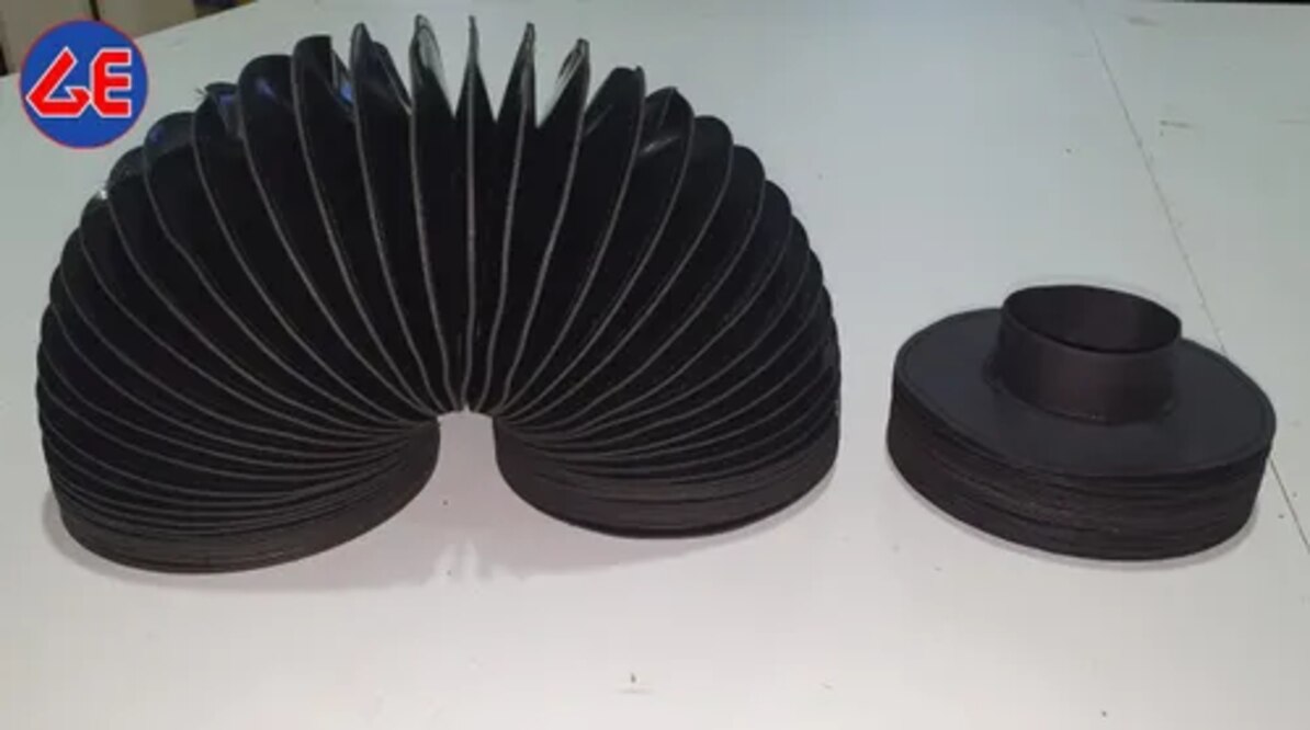
- Check the fold geometry. If the fold pitch is P and the design uses N convolutions, compare the supplier’s actual collapsed and extended length per convolution; fabric thickness, reinforcement and fold height prevent a universal N × P formula.
- Verify the effective cross-section against the screw, ball nut, return tubes, lubrication fittings and clamps. Screw diameter alone cannot define the cover.
Use the calculated Lc, Le, usable travel and fold height when requesting ball screw bellow covers for specifications. If the available retracted pocket is shorter than Lc, change the fold design or mounting arrangement rather than compressing the cover beyond its stated limit.
Obtain both lengths on the quotation, because two covers with the same extended length can have different usable travel and sag resistance.
Choose the mounting arrangement and construction for the machine
The mounting arrangement determines whether the cover follows the ball nut or stays anchored to the machine. State the fixed end, moving end, mounting depth, attachment method, hole pattern, bolt size, flange dimensions, and whether removal must be possible without taking out the screw or nut.
| Option | What it means | Specification consequence |
|---|---|---|
| Fixed to moving nut | One end travels with the nut while the other anchors to the machine | Check nut width, height, lubrication port, attachment clearance, and the nut’s complete envelope |
| Fixed to machine structure | The cover remains attached to fixed faces as the screw operates inside it | Confirm both end faces, available collapsed-length space, and clearance at each travel limit |
| End frames or flanges | Rigid frames provide a defined interface at one or both ends | Give frame thickness, outside dimensions, hole centres, bolt access, and sealing or clamping details |
End folds and terminal reinforcement reduce the usable opening. Measure the actual opening against the ball-nut envelope, screw-support bearing, and lubrication fittings; nominal inside width alone can produce interference.
Choose fabric and coating from the actual exposure. Coolant, cutting oil, alkaline cleaners, hydrolysis, heat, ultraviolet light, and ozone can affect polyurethane-coated fabric, silicone-coated fabric, and elastomer-coated fabric differently. Ask for the temperature and chemical-resistance limits of the proposed construction.
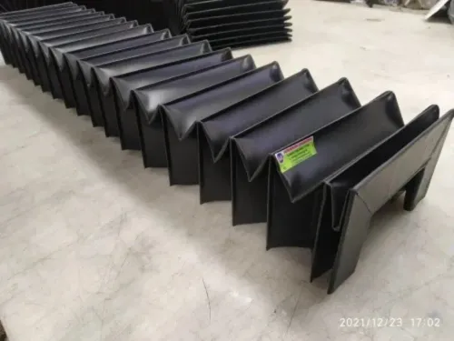
Horizontal ball screw bellows for machine tools may sag into the rotating screw. Specify reinforced folds, guide strips, internal support rings, or an intermediate support when the span demands them; increasing width alone does not reliably prevent contact. These details belong on the drawing for custom ball screw bellow covers.
Check speed, coolant, sag and rubbing across the full stroke
A cover that clears a stationary screw can still fail at operating speed. Specify the internal opening around the largest dynamic envelope, including nut movement, screw whip, eccentricity, assembly tolerance and thermal growth. Check clearance through the complete stroke, especially at both reversal points; rubbing at an end fold quickly becomes abrasion, heat and fatigue.
Send the supplier these operating conditions before selecting ball screw bellows for machine tools:
- Maximum screw speed, acceleration, cycle frequency and expected service life
- Horizontal, vertical or inclined orientation, plus the travel direction
- Actual coolant, cutting oil, oil mist, cleaning chemical and chip type
- Ambient and washdown temperature, UV exposure and ozone exposure
- Clearance measured while jogging and running the axis at its maximum speed
| Condition | Failure risk | Design check |
|---|---|---|
| Horizontal span | Gravity sags folds into the screw or structure | Measure sag across the full extended length; consider guide strips, support rings, reinforced folds or an intermediate support |
| High speed or acceleration | Fold flutter, rubbing and fatigue | Confirm the cover does not balloon, twist or contact the screw during acceleration and reversal |
| Coolant and chemicals | Coating swelling, hydrolysis, cracking or delamination | Match the fabric-coated elastomer, polyurethane-coated fabric or silicone-coated fabric to the actual fluids and temperature |
| Tight end clearance | Nut or fold strikes the frame at travel limits | Jog to both ends with the cover installed, then verify clearance after thermal growth |
Increasing nominal width does not reliably cure horizontal sag. Custom ball screw bellow covers need dynamic clearance and material selection based on the machine’s real duty, not ball-nut dimensions alone.
Give a local supplier a drawing and measurable acceptance criteria
Send the ball screw bellow cover supplier one dimensioned drawing, not only photographs. Mark the machine datums, screw centreline, travel limits, nut envelope, obstructions, mounting faces, and the space available at both fully compressed and fully extended positions. Add photographs with arrows for unclear features.
1. State the screw outside diameter, ball-nut length, width and maximum height, return tubes, lubrication fittings, wipers, clamps, required protected travel, collapsed length, extended length, fold count and fold pitch.
2. Specify which end is fixed and which moves. Include flange or end-frame dimensions, hole pattern, bolt size, clamp or collar arrangement, mounting depth, overlap, and whether removal must be possible without taking off the ball nut or screw.
3. Identify the construction and environment: coolant type, oil mist, chips, abrasive dust, heat, cleaning chemicals, operating speed, acceleration and vertical or horizontal orientation. Record any old-cover failure, such as fold fatigue, rubbing, torn attachments or coolant swelling.
A local manufacturer such as GURUKRUPA BELLOWS PVT LTD can work from this information, but call the request “custom ball screw bellow covers” only after the interface is defined; the screw’s nominal diameter does not size the cover.
Before acceptance, compare the delivered cover with the approved drawing. Measure collapsed and extended lengths, fold pitch, frame dimensions and hole centres. Install it and move the axis through the complete stroke at clearance-critical positions.
Reject it if any fold, frame or attachment rubs, the cover bottoms out before travel ends, the nut envelope contacts the fabric, or the mounting holes force distortion. For replacement work, verify the original failure cause has disappeared, not merely that the new cover matches its old length.
Frequently asked questions
What dimensions are needed to specify a ball screw bellow cover?
Measure the complete moving envelope around the screw nut, including return tubes, clamps and bearing supports, at both travel limits.
How do you calculate compressed length, extended length and usable travel?
Record the machine’s two end positions, then define the cover’s compressed and extended lengths so the required usable travel remains clear of fixed components.
What mounting and construction details should you provide?
Specify the mounting faces, attachment method, cover shape, reinforcement, material and protection required for the machine’s coolant, heat and debris conditions.
What should you check across the full ball screw stroke?
Check speed, coolant exposure, sag, folding behavior, rubbing and clearance at several positions across the complete stroke.
What should a local ball screw bellow cover supplier receive?
Provide a dimensioned drawing, machine photographs, operating conditions and measurable acceptance criteria for fit, travel, clearance and movement.