
Fly ash loading fails when the spout, gate, tanker connection, and dust-extraction path are treated as one generic hose. By following the material path and air path separately, you can identify how the equipment extends, fills, shuts off, retracts, and contains dust without confusing a flexible cover with a pressure-rated conveying line.
Key takeaways
- Match the bellow design to gravity, pneumatic, or vehicle loading.
- Use dust extraction and sealed connections to control fly ash during discharge.
- Specify wear sections, suspension, and replacement parts before installation.
- Check the silo gate, loading spout, tanker hatch, and extraction path as one system.
What the Loading Bellow Covers and How the Equipment Connects
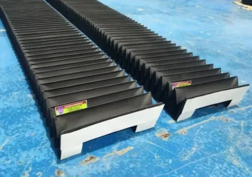
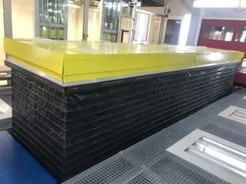
A fly ash bulk loading bellow cover is a flexible, telescoping enclosure fitted below a silo outlet. It surrounds the moving loading connection as the outlet travels down to a receiving vehicle, containing dust and accommodating changes in height. “Loading spout” describes the complete extendable assembly; “cover” describes its flexible outer bellows.
Fly ash does not normally travel through the fabric folds. It falls through an internal chute or sleeve, while the outer bellows protects the joint and maintains an enclosed connection.
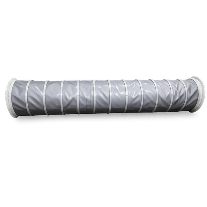
This is why a fly ash loading spout bellow is not a pressure-rated conveying hose: the upstream feeder establishes solids flow, while the spout provides reach and dust containment.
The route starts at the silo outlet and ends at the tanker hatch, with feeding equipment and the telescoping spout between them. A suspension cable raises and lowers the spout, while a winch sets its position. The lower sealing end seats against the hatch and absorbs positioning error during vehicle placement.
Loading also moves air. As fly ash enters, displaced dusty air leaves the tanker, so effective bellow covers for bulk loading use a separate extraction or dust-return passage near the loading head. That passage routes air to a filter instead of forcing it through fabric folds or releasing it around the hatch.
The Filling Sequence from Silo Gate to Tanker Hatch
To understand how fly ash loading for bellow covers work, follow the product path and the moving enclosure separately. The fly ash loading spout bellow telescopes around an internal chute; the chute carries ash, while the bellows accommodates the changing distance between the silo outlet and tanker hatch.
1. Park the loading spout above the loading point, then start dust extraction if the system uses a separate return passage. Lower or extend the spout with its winch, cable, or chain suspension until the outlet cone, skirt, or cuff engages the tanker hatch.
2. Confirm that the hatch connection is seated and that the extraction path is open. Open the silo slide gate, rotary valve, or feeder gradually so ash enters the inner chute without shocking the lower wear section or overwhelming the tanker’s displaced-air route.
3. Continue feeding until the level sensor signals a full tanker or the control system reaches the preset batch quantity. A timer alone cannot confirm fill level: bridging, an offset inlet, or a blocked sensor can leave the vehicle underfilled while the feeder continues running.
4. Stop the feeder, let extraction clear suspended dust, and close the product gate. Raise the spout only after product flow has stopped; then inspect the lower cone and folds for trapped ash before returning the bellow to its parked position. Clean or empty deposits that add weight, restrict telescoping, or abrade the fabric.
Gravity, Pneumatic and Vehicle Loading Require Different Designs
Gravity loading lets the upstream slide gate, rotary feeder, and outlet diameter establish throughput; the bellows does not meter fly ash. Free-falling ash strikes the lower cone and receiving hatch, so abrasion, impact, and dust leakage concentrate at the bottom. A replaceable wear section lasts better than making every fold from heavy fabric.
Pneumatic loading adds conveying velocity, pressure differences, and turbulence. Fine ash can scour bends, migrate into folds and cable tracks, and plug narrow passages when airflow falls. Size the internal sleeve and fly ash equipment bellows for solids rate, bulk density, conveying velocity, temperature, and telescoping stroke; do not throttle flow by collapsing the cover.
Vehicle loading adds movement and alignment risk. A truck, railcar, or container can shift against the outlet during positioning, while hatch diameter and height determine the required extension. If the lower section cannot tolerate contact, the cover can tear or lose its seal even when the ash flow is correct.
Use this checklist before choosing fly ash bulk loading bellow covers:
- Confirm feeder capacity, outlet diameter, ash bulk density, temperature, and abrasive fraction.
- Provide a separate dust-return or extraction passage so displaced air does not escape through folds.
- Match retracted and extended lengths to hatch geometry and suspension travel.
- Specify a reinforced, replaceable lower wear section with inspection access above it.
- Check grounding, sensor clearance, and the replacement method for lifting cables, chains, or sleeves.
Dust Extraction, Sealing and Ignition Control During Discharge
The loading point should pull displaced air into a filter, not push it through the fabric folds or around the tanker hatch. Bellow covers for bulk loading commonly include a separate dust-return or extraction passage near the loading head, sized from displaced-air volume, leakage points, and required capture velocity rather than spout diameter alone.
The fly ash loading spout bellow must seal against the receiving inlet while it transfers solids. Keep the hatch connection, flexible sleeve, and extraction line aligned; a damaged seal releases fine ash, while excessive negative pressure draws ash into folds, disturbs the stream, or collapses an inner sleeve.
Balance airflow with the feeder and outlet diameter.
Control these conditions as one system:
- Bond the silo, spout, tanker, and extraction duct, then verify a continuous grounding path before opening the gate.
- Use conductive or static-dissipative flexible parts where the hazard assessment requires them; fabric alone does not control static.
- Match bellow materials, seals, wear sections, and sensors to the actual bulk temperature and ash chemistry. Heat-softened seals leak first.
- Treat fly ash as a potential combustible dust when unburned-carbon content and test results identify that hazard. Provide ignition-source control and the specified explosion protection for the complete loading installation, not just the bellow.
- Keep the extraction pressure stable. Too little capture vents dust at the hatch; too much pulls fines into seams and mechanisms.
Do not blast settled ash from the bellow with compressed air: it can create an ignitable dust cloud. Use vacuum extraction or the approved low-dust cleaning method in the site procedure.
How to Specify Wear Sections, Suspension and Replacement Parts
Specify the bellow against the actual loading cycle, not the nominal diameter. Record how fly ash loading for bellow covers work in practice: the retracted and extended lengths, required stroke, outlet diameter, loading rate, bulk density, ash temperature, and ash chemistry. Include the receiving-hatch diameter, vehicle movement, dust-extraction port, sensor positions, and grounding route.
Compare these construction details before ordering:
- Wear section: replaceable abrasion-resistant lower cone versus one-piece fabric. The lower end receives falling ash, hatch impact, and vehicle contact; a replaceable section limits the cost and duration of repairs.
- Suspension: cable, chain, or guided lifting frame. Check available headroom, side loads, winch capacity, travel stops, and access for cleaning fine ash from folds and tracks.
- Internal passage: smooth chute or sleeve with reinforced seams and inspection access above the outlet. Fly ash equipment bellows fail early when ash enters seams, bends, or lifting mechanisms.
- Spares: lower wear cone, flexible sections, clamps, seals, cables, pulleys, sensors, and grounding straps. Ask for part numbers, dimensions, material specifications, and replacement instructions.
| Option | Compare | Consequence |
|---|---|---|
| Replaceable wear cone | Local replacement | Shorter maintenance shutdown |
| One-piece heavy bellows | Whole-cover replacement | Higher replacement effort after lower-end wear |
| Separate extraction passage | Return air to filter | Less dust leakage through folds |
GURUKRUPA BELLOWS PVT LTD can be compared on this basis: request a drawing showing interfaces, suspension points, extraction connection, sensor access, and every replaceable part.
Related products
 | Fly Ash Bulk Loading Spot Bellow Fly Ash Bulk Loading Spot Bellow ₹10000 Product Details: Minimum Order Quantity 01 Number Brand GURUKRUPA Size ANY We manufacture a wide range of Fly Ash Bulk Loading Spot Bellow in various... View product → |
 | Cement Plant Bulk Loading Unloading Bellows Cement Plant Bulk Loading Unloading Bellows ₹5000 Product Details: Brand GURUKRUPA Size ANY Having rich experience and thorough understanding of the market operations, we are engaged in manufacturing... View product → |
Frequently asked questions
What does a fly ash loading bellow cover?
It is the flexible outer bellows around a telescoping loading spout below a silo outlet. The cover encloses the moving connection as it reaches the receiving vehicle.
How does fly ash move from the silo to a tanker?
The sequence runs from the silo gate through the loading spout and into the tanker hatch. The spout extends to the vehicle connection, then retracts after filling and disconnection.
Why do gravity and pneumatic fly ash loading systems need different bellow designs?
Gravity loading relies on material falling through the outlet, while pneumatic loading uses conveying air. Vehicle loading also adds movement and changing height, so the spout and cover must suit the force, travel, and connection conditions.
What should you specify when replacing a fly ash loading bellow cover?
Specify the wear sections, suspension arrangement, dimensions, travel, connection points, and replacement parts. Include the loading method and the dust-extraction and sealing arrangement.